4.1. n-vector explained
4.1.1. What is n-vector?
n-vector is just the 3D normal vector to the Earth ellipsoid (or sphere, if spherical Earth model is used). It can replace latitude and longitude (and other alternatives) to represent horizontal position, giving several advantages. This page gives a brief introduction, see Gade (2010). for a more detailed explanation.
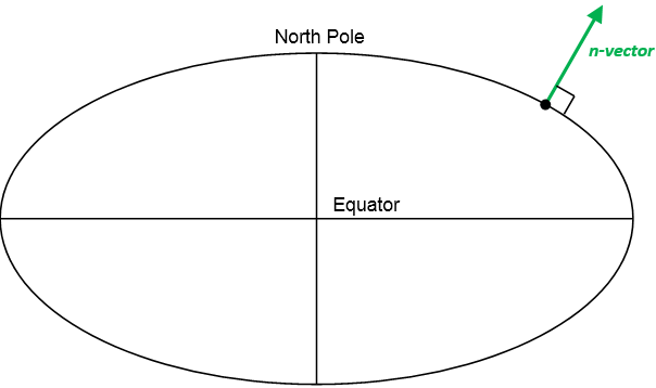
Fig. 4.1 The n-vector is the normal vector to the Earth model (reference ellipsoid).
4.1.2. Why is n-vector needed?
Performing global position calculations often involves one or more of the following concerns:
Complex implementations (many, and often complex lines of program code needed)
Approximations, e.g.
distortion in map projections
assuming spherical Earth when ellipsoidal should be used Errors often increase with increasing distances
Equation/code not valid/accurate for all Earth positions, e.g.
Latitude/longitude:
Singularities at Poles
Discontinuity at International Date Line (
meridian)
Map projections: usually valid for a limited area, e.g. UTM
Iterations (need to iterate to achieve needed accuracy)
By using the solutions provided here, these concerns can be avoided for a majority of position calculations.
4.1.2.1. What can go wrong if using latitude and longitude?
Even the simple discontinuity of longitude at the International Date Line
( meridian) can give serious consequences if not handled
correctly in all the code. An example illustrating this was the computer
crash experienced by 12 fighter aircrafts (F-22 Raptors)
when they crossed this meridian in 2007.

Fig. 4.2 The discontinuity of longitude caused serious problems for the F-22 Raptors when the longitude instantly changed from  to
to  (when crossing the International Date Line).
The discontinuity can be quite easily handled by adding specific code, while the singularities at the Poles are much more challenging to deal with. Examples of how the singularities can affect calculations with latitude and longitude are found in Section 6 of the reference Gade (2010).
4.1.3. n-vector
As discussed above, using latitude and longitude in calculations may lead to
several problems due to the singularities at the Poles and complex behavior
near the Poles, and due to the discontinuity at the Date Line ( meridian).
Instead of latitude and longitude, we represent position with an “n-vector”, which is the normal vector to the Earth model (the same reference ellipsoid that is used for latitude and longitude). When using n-vector, all Earth-positions are treated equally, and there is no need to worry about singularities or discontinuities. An additional benefit with using n-vector is that many position calculations can be solved with simple vector algebra (e.g. dot product and cross product).
In documents we use  , while in program code we use n_E.
E denotes an Earth-fixed
coordinate frame, and it indicates that the three components of n-vector are
along the three axes of E. More details about the notation used are found here.
The position of the North Pole given as n-vector is
, while in program code we use n_E.
E denotes an Earth-fixed
coordinate frame, and it indicates that the three components of n-vector are
along the three axes of E. More details about the notation used are found here.
The position of the North Pole given as n-vector is

(assuming the coordinate frame E has its z-axis pointing to the North Pole). For all the details about n-vector, see the reference Gade (2010).
4.1.4. Converting between n-vector and lat/lon
Converting between n-vector and latitude/longitude is done using
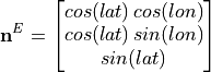
This can be seen from the geometry and the axes of E. The relation is true both for ellipsoidal or spherical Earth model.
To find latitude from n-vector we have

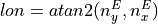
where the x, y and z subscripts indicate elements 1, 2 and 3 of the n-vector. Note that the atan2-variant has better numerical properties, and is thus recommended for implementation.
Longitude is found from
In the nvector library, two functions lat_lon2n_E and n_E2lat_lon are used for these conversions.
4.1.5. Many position calculations can be solved with only two functions
It turns out that very often, the problem to be solved is one of these:
A and B => delta: Given two positions, A and B (e.g. as latitudes/longitudes/heights), find the (delta) vector from A to B in meters. See also Example 1.
A and delta => B: Given position A (e.g. as lat/long/height) and a vector in meters from A to B, find position B. See also Example 2.
Two functions performing these calculations are available here, using n-vectors for
position A and B as input/output. The n-vectors for position A and B are written
 and
and  while in program code we use n_EA_E and n_EB_E. The (delta) position
vector from A to B is written
while in program code we use n_EA_E and n_EB_E. The (delta) position
vector from A to B is written  (p_AB_E).
More info about the notation is found in the next section.
(p_AB_E).
More info about the notation is found in the next section.
Based on the above variable names, the two above functions are called:
n_EA_E_and_n_EB_E2p_AB_E
n_EA_E_and_p_AB_E2n_EB_E
4.2. Vector symbols explained
The notation system used for the n-vector library is presented in Chapter 2 of the following thesis: Gade (2018): “Inertial Navigation - Theory and Applications”. A simplified presentation is given here.
4.2.1. Coordinate frame
A coordinate frame has a position (origin), and three axes (basis vectors) x, y and z (orthonormal). Thus a coordinate frame can represent both position and orientation, i.e. 6 degrees of freedom. It can be used to represent a rigid body, such as a vehicle or the Earth, and it can also be used to represent a “virtual” coordinate frame such as North-East-Down.
Coordinate frames are designated with capital letters, e.g. the three generic coordinate frames A, B, and C.
We also have specific names for some common coordinate frames:
Coordinate frame |
Description |
E |
Earth |
N |
North-East-Down |
B |
Body, i.e. the vehicle |
4.2.2. General vector
A 3D vector given with numbers is written e.g.
 .
The three numbers are the vector components
along the x, y and z axes of a coordinate frame. If the name of the vector is k, and the
coordinate frame is A, we will use bold k and A as trailing superscript, i.e.:
.
The three numbers are the vector components
along the x, y and z axes of a coordinate frame. If the name of the vector is k, and the
coordinate frame is A, we will use bold k and A as trailing superscript, i.e.:

Thus  is the 3D vector that is constructed by going
2 units along the x-axis of coordinate frame A, 4 units along the y-axis, and 6 along
the z-axis. We say that the vector k is decomposed in A.
is the 3D vector that is constructed by going
2 units along the x-axis of coordinate frame A, 4 units along the y-axis, and 6 along
the z-axis. We say that the vector k is decomposed in A.
4.2.3. Position vector
Instead of the general vector k, we can have a specific vector that goes from A to B. This vector can be decomposed in C. A, B, and C are three arbitrary coordinate frames. We would write this vector:

In program code: p_AB_C
The letter p is used since this is a position vector (the position of B relative to A, decomosed/resolved in the axes of C).
Example a):
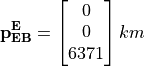
From the subscript we see that this is the vector that goes from E (center of the Earth) to B (the vehicle). The superscript tells us that it is decomposed in E, which we now assume has its z-axis pointing towards the North Pole. From the values we see that the vector goes 6371 km towards the North Pole, and zero in the x and y directions. If we assume that the Earth is a sphere with radius 6371 km, we see that B is at the North Pole.
Example b):
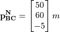
The vector goes from B, e.g. an aircraft, to C, e.g. an object. The vector is decomposed in N (which has North-East-Down axes), i.e. C is 50 m north of B and 60 m east, and C is also 5 m above B.
4.2.4. Properties of the position vector
For the general position vector , we have the property:

I.e. swapping the coordinate frames in the subscript gives a vector that goes in the opposite direction. We also have:

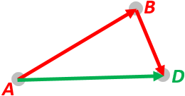
I.e., going from A to D is the same as first going from A to B, then from B to D. From the equation, we see that B is cancelled out. A, B, C, and D are arbitrary coordinate frames.
4.2.5. Rotation matrix
If we return to the general vector , we could also have a coordinate
frame B, with different orientation than A. The same vector k could be expressed by components along
the x, y and z-axes of B instead A, i.e. it can also be decomposed in B, written  .
Note that the length of equals the length of .
We will now have the relation:
.
Note that the length of equals the length of .
We will now have the relation:
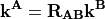
 is the 9 element (3x3) rotation matrix (also
called direction cosine matrix) that transforms vectors decomposed in B to
vectors decomposed in A. Note that the B in .
should be closest to the vector decomposed in B (following the
“the rule of closest frames”, see Section 2.5.3 in “Inertial Navigation - Theory and Applications”
for details). If we need to go in the other direction we have:
is the 9 element (3x3) rotation matrix (also
called direction cosine matrix) that transforms vectors decomposed in B to
vectors decomposed in A. Note that the B in .
should be closest to the vector decomposed in B (following the
“the rule of closest frames”, see Section 2.5.3 in “Inertial Navigation - Theory and Applications”
for details). If we need to go in the other direction we have:
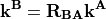
Now we see that A is closest to A.
4.2.6. Properties of the rotation matrix
We have that
where the T means matrix transpose. We also have the following property (closest frames are cancelled):
If we compare these properties with the position vector, we see that they are very similar: minus is replaced by transpose, and plus is replaced by matrix multiplication. A, B, and C are three arbitrary coordinate frames.
4.2.7. n-vector
The n-vector is in almost all cases decomposed in E, and in the simplest form we will write it

This simple form can be used in cases where it is no doubt about what n-vector expresses the position of. In such cases we can also express the position using the variables lat and lon, without further specification.
However, if we are interested in the position of multiple objects, e.g. A and B, we must specify which of the two, both for n-vector and for latitude/longitude. In this case we will write:
and (program code: n_EA_E and n_EB_E)
And
 and
and 
The subscript E might seem redundant here, it could be sufficient to use only A or B.
However, we have chosen to also include the E, since both n-vector and latitude/longitude
are depending on the reference ellipsoid that is associated with E (see Section 4.1. in
Gade (2010)
for more about this). Note however, that the subscript rules (swapping and cancelling)
we had for  and
cannot be used for n-vector or lat/lon.
and
cannot be used for n-vector or lat/lon.
For spherical Earth, we have a simple relation between  and
and
 :
:

where  is the radius of the Earth,
  is the height of B and
  is
the depth. For more information about how to use n-vector in various calculations, see the 10 examples
and Gade (2010).
is
the depth. For more information about how to use n-vector in various calculations, see the 10 examples
and Gade (2010).